Binary Logic

Computers use binary and logic gates to make calculations.
Binary is in 1s and 0s. 1 represents ON and 0 represents OFF. You can use these basic inputs/outputs and boolean logic to create system for operations.
Binary is used because circuit only check for two states which are 1 or 0.
You will also need to understand and produce simple logic diagrams using the operations NOT, AND and OR.
| Gate | Picture | Function | NOT | 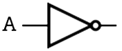 |
If the input is 1 this gate will output 0.If the input is 0 this gate will output 1. |
|---|---|---|
| AND | 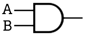 |
Outputs 1 ONLY if both A and B are 1. Otherwise outputs 0. |
| OR | 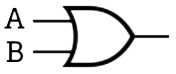 |
Outputs 1 if AT LEAST one of the inputs is 1. Otherwise outputs 0. |
You must also know how to draw out their truth table.
Not truth table
| A | Q (Output) | 1 | 0 |
|---|---|
| 0 | 1 |
And truth table
| A | B | Q (Output) | 1 | 1 | 1 |
|---|---|---|
| 1 | 0 | 0 |
| 0 | 1 | 0 |
| 0 | 0 | 0 |
OR truth table
| A | B | Q (Output) | 1 | 1 | 1 |
|---|---|---|
| 1 | 0 | 1 |
| 0 | 1 | 1 |
| 0 | 0 | 0 |